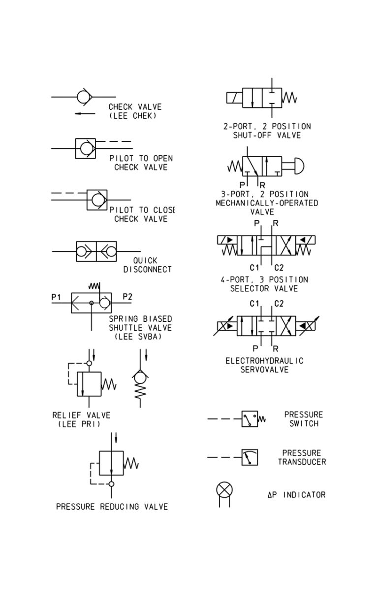
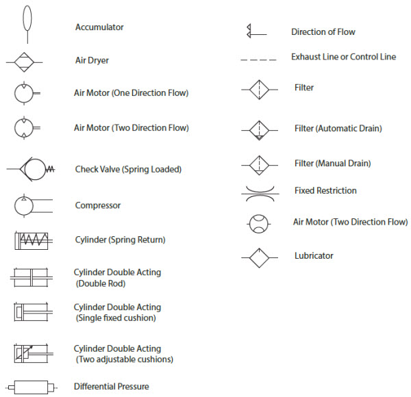
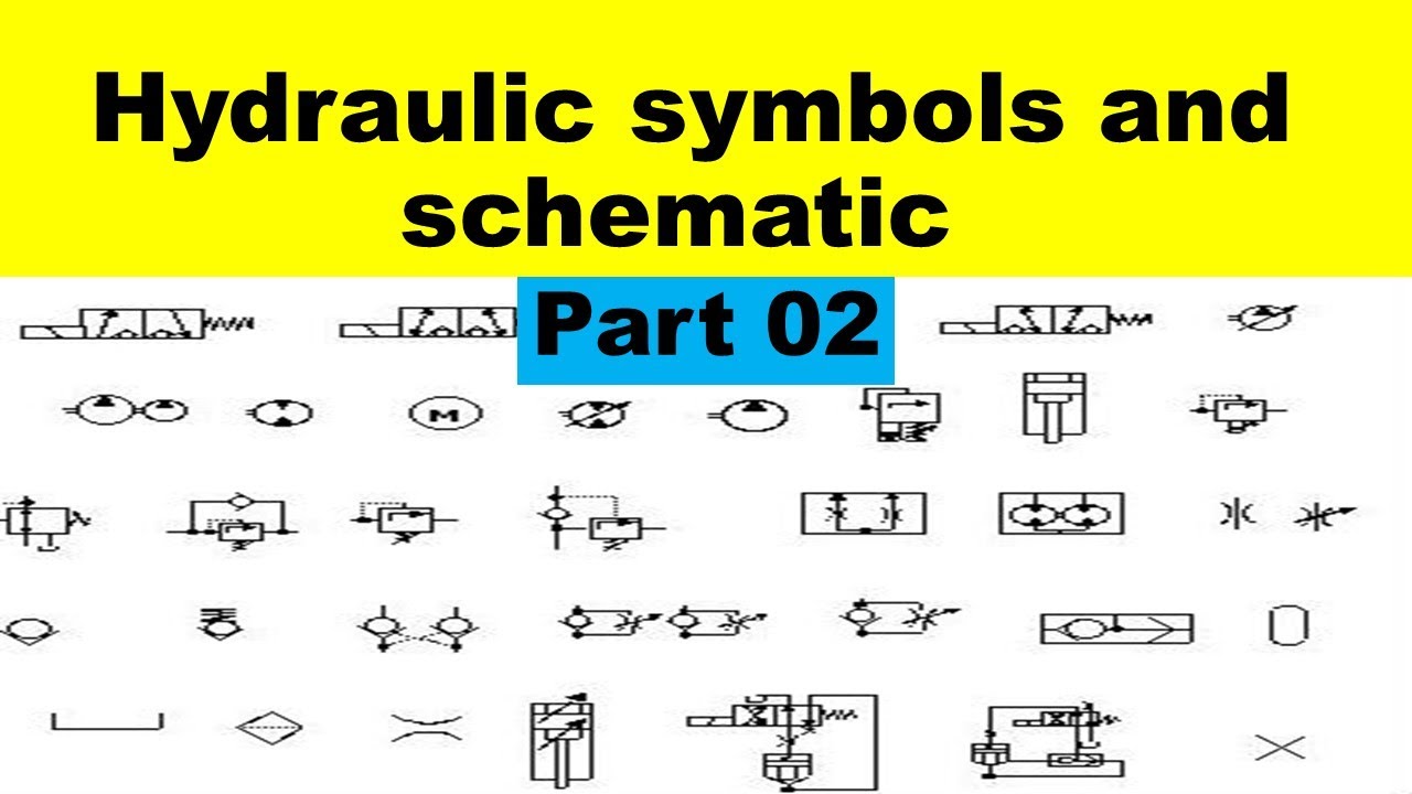
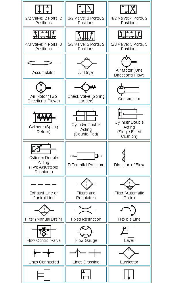
Hydraulics and Pneumatics Symbols The Lee Company
Reference Information Hydraulics and Pneumatics Symbols Common hydraulic and pneumatic symbols used to represent components in fluid system diagrams.
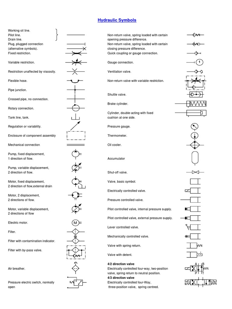
Hydraulic Symbols
Hydraulic symbols are a standard designed to provide a clear representation of how each hydraulic component functions in a hydraulic system. Hydraulics engineers regularly encounter these diagrams, but these symbols can be daunting to interpret if you have limited experience with schematics and the fluid power industry.

A guide to common hydraulic symbols EngineeringClicks
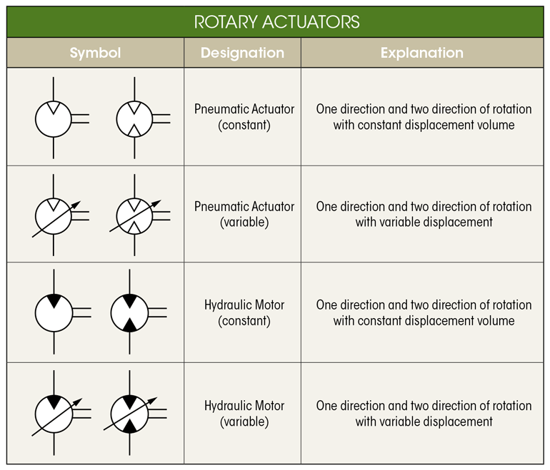
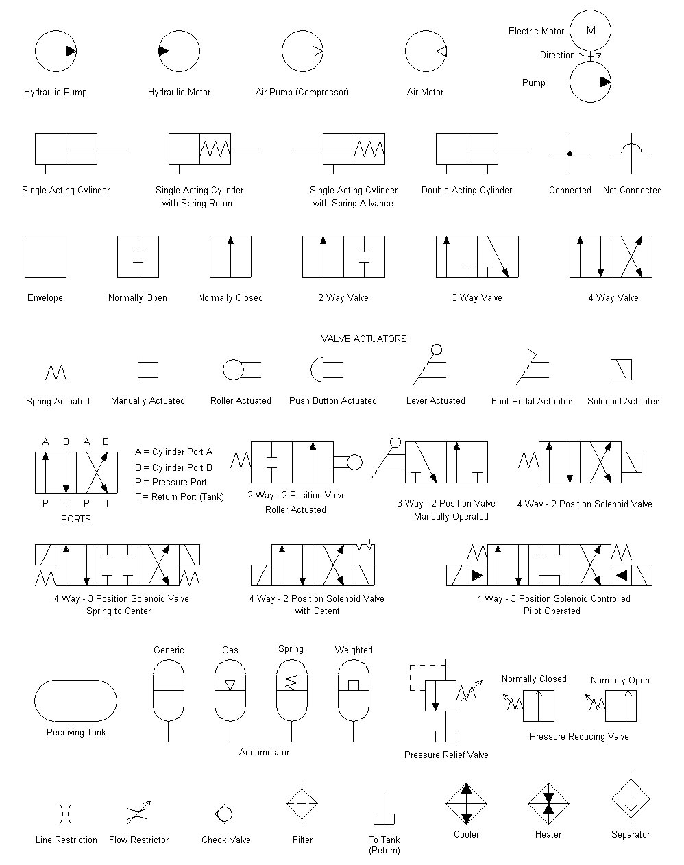
These are the circle, square and diamond. Ninety nine percent of hydraulic symbols use one of these three as a foundation. Pumps and motors of every kind are drawn using a circle, as are measuring instruments. Valves of every kind use the basic square as a start.
Fluid Power Systems Hydraulic System Working Instrumentation Tools
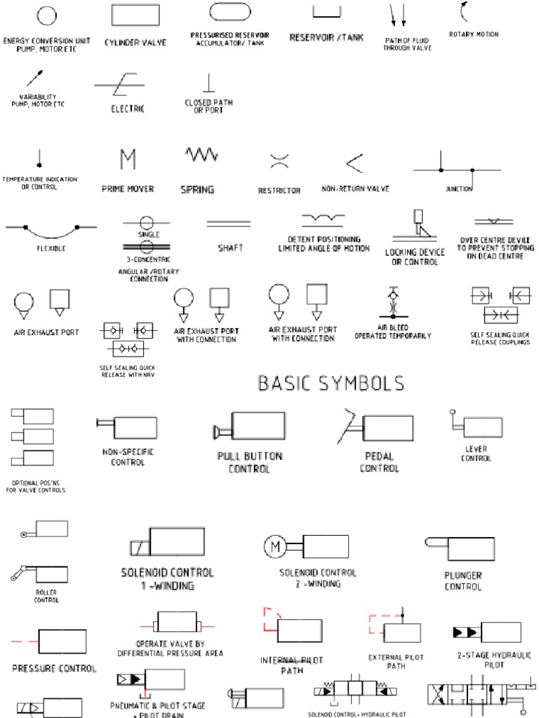
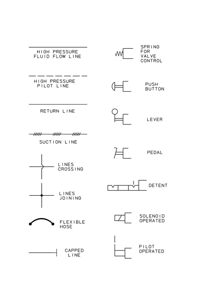
Working hydraulic line Pilot line Drain line Direction of flow Hose or other flexible working line Lines crossing (no connection) Lines connecting Fixed) throttle, lines with fixed restriction Adjustable flow control valve (Throttle Valve) Temperature compensated flow control valve Orifice Replaceable orifice Plug in place of replaceable.
What’s the Difference Between Hydraulic Circuit Symbols? Machine Design
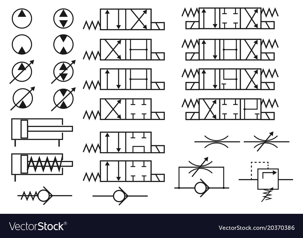
The chart below shows many of the symbols (letters) in the language of fluid power. By learning these symbols, it will be possible to construct or identify most fluid power components. For example, the seven symbols below can be rearranged in several ways to describe very different components. basics circuit hydraulic symbols
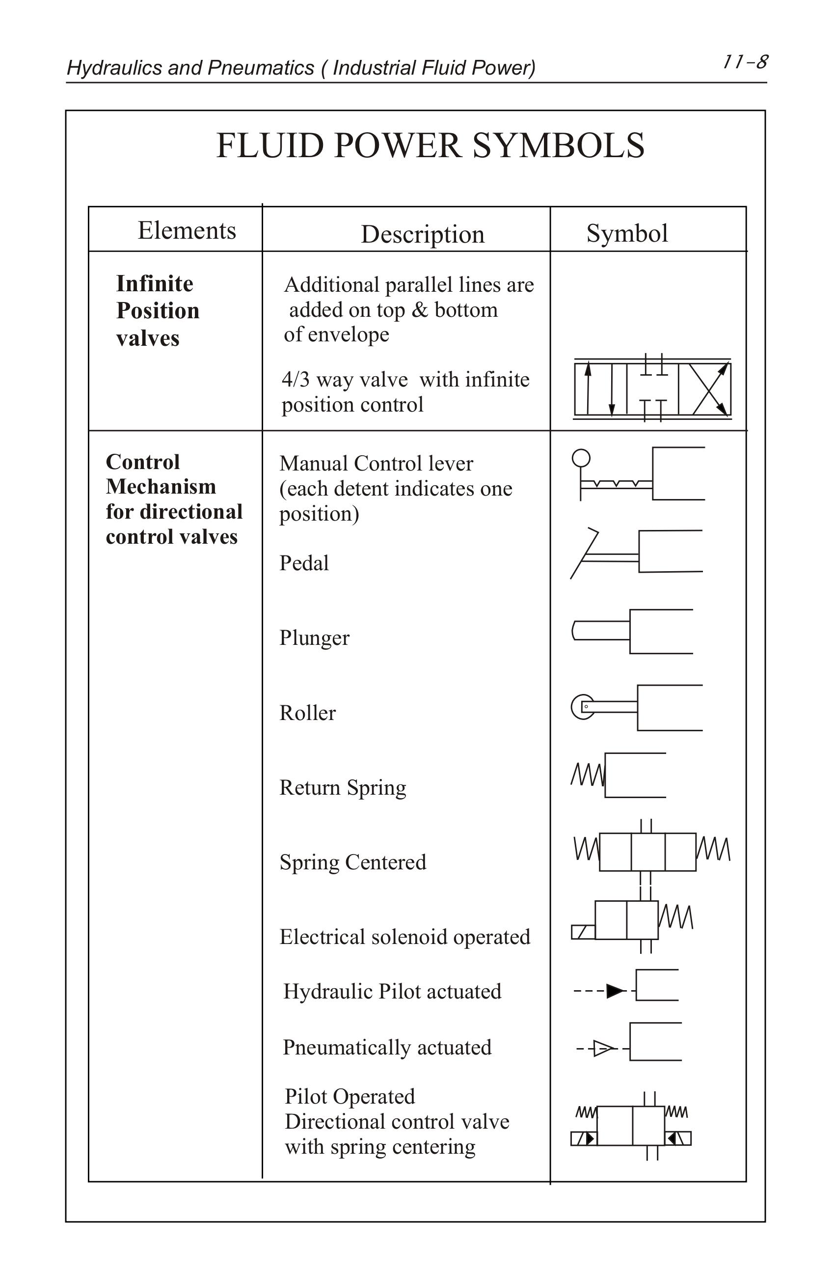
Hydraulic Valve Symbols Autocad
Technical Knowledge Hub Hydraulic Symbols Hydraulic circuits can be comprised of an infinite combination of cylinders, motors, valves, pumps and other equipment connected via hydraulic pipes and tubes.
Hydraulic Symbols
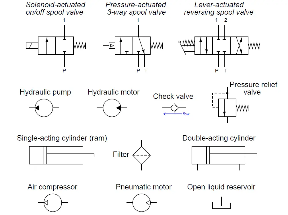
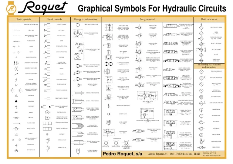
Basic symbols "Your One-Stop Hydraulics Resource" Call us now or— UK: 084Y644 3640 International: + 44 845 644 3640 Spool controls Graphical Energy transformation FIXED DISPLACEMENT PUMP SINGLE-ACTING HAND PUMP (e.g. 376) DOUBLE ACTING HAND PUMP (e.g. 27906) FIXED DISPLACEMENT REVERSIBLE MOTOR WITHOUT DRAIN FIXED DISPLACEMENT REVERSIBLE
Hydraulics Pneumatics Symbols
Hydraulic Symbols. To enable engineers to communicate and understand the circuitry associated with hydraulic systems there is an International Standard for hydraulic symbols - ISO1219/1 2006. Circuit diagrams enable the reader to identify the valve type and function and in certain cases, their locations relating to other components.
Hydraulic & Electric Symbols Valve Technology
Hydraulic Symbols. LINES. Line, Working ( Main ) Line, Pilot (For Control) Line, Enclosure Outline . Direction of Flow - Hydraulic. Component (Run Arrow Through Symbol at 45°) Pressure Compensated Units (Arrow Parallel to Short Side of Symbol) Temperature Cause or Effect . Reservoir Vented. Reservoir Pressurized . Line, to Reservoir Above.
Hydraulic Symbols and Schematic For Beginners How to Read Hydraulic
Reading fluids circuit diagrams - hydraulic & pneumatic symbols Dec 19, 2017 Below are some common illustrations of equipment located on fluids circuit diagrams, followed by descriptions of the most common elements. Later in this article series we will describe some simple hydraulic and pneumatic circuits composed of these circuit elements.
Hydraulic symbols Lys for
In a hydraulic system schematic, the pipes, hose and tube assemblies are represented by lines. A number of different types of lines are used to represent different types of assemblies. As with all other hydraulic symbols, these symbols are issued and controlled by The International Standards Organization (ISO), standard ISO 1219-1:2012.
Hydraulics and Pneumatics Symbols The Lee Company
For port identification and operator marking see iso 9461 (hydraulic) or bs iso 5599 (Pneumatic). graphic symbols for fluid power systems general engineering hydraulic & PNEuMaTic SyMBOlS supply lines, return lines, component enclosure, symbol enclosure Pilot (control) line, drain line, flushing line, bleed line Electrical control line Frame.
Set of hydraulic symbols Royalty Free Vector Image
Learn the fundamentals of hydraulic systems and components with Parker's training course on basic hydraulics. This PDF file covers topics such as hydraulic principles, symbols, pumps, valves, cylinders, motors, and maintenance. Download it for free and enhance your skills and knowledge in industrial hydraulics.
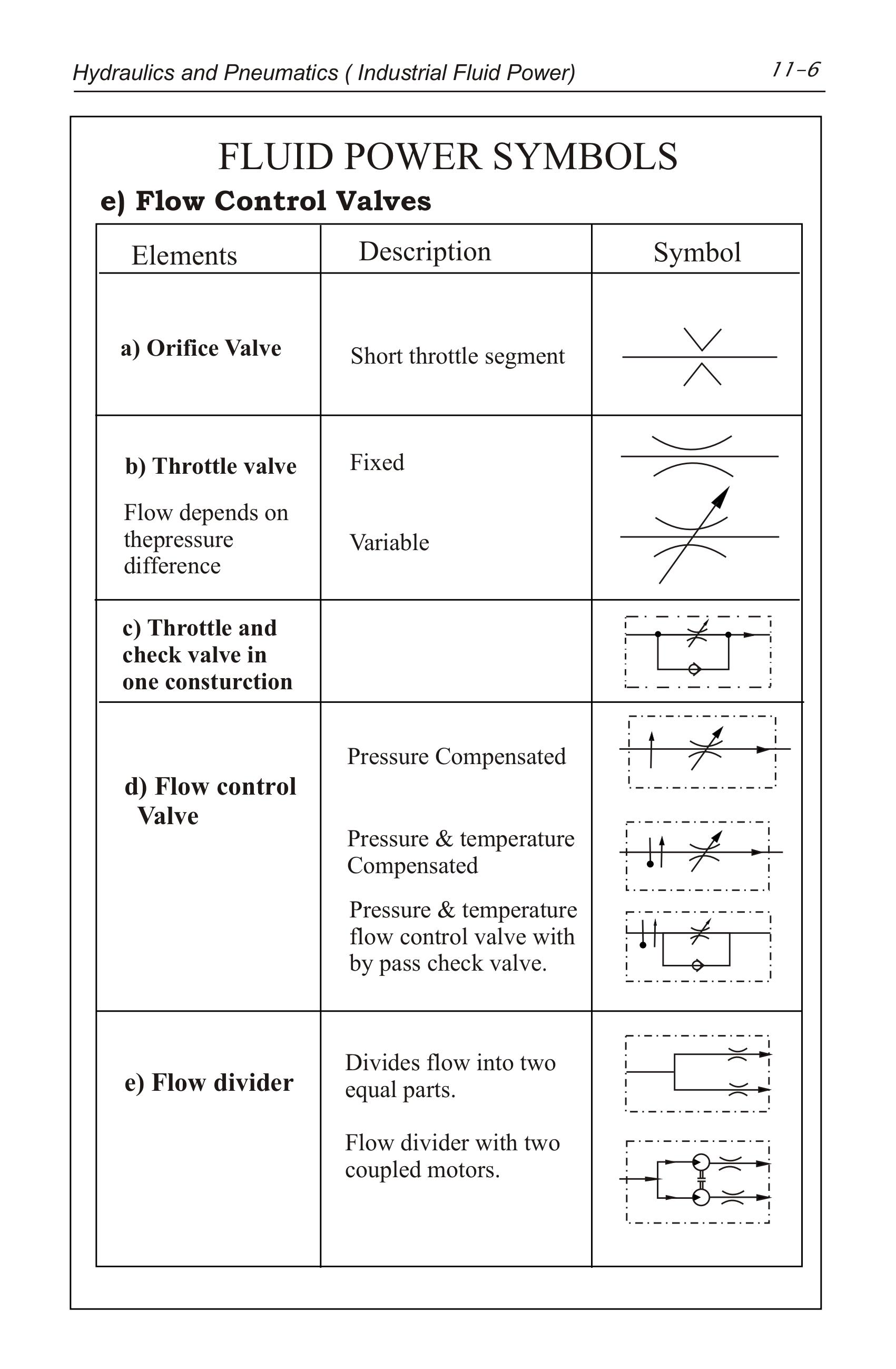
Flow Control Valves Hydraulic Symbology 204
Basic Symbols Working hydraulic line Pilot line Drain line Direction of flow Hose or other flexible working line Lines crossing (no connection) Lines connecting Fixed throttle, lines with fixed restriction Adjustable flow control valve (Throttle Valve) Temperature compensated flow control valve Vented reservoir Pressurised reservoir

Hydraulic Symbols
Below we have summarised some of the most common symbols you may come across. Our technical sales engineers will be happy to help should you need any further help and assistance. Please get in touch on +61 8 8984 4939. Accumulator Symbols Download PDF Cylinder Symbols Download PDF Lines and Basic Symbols Download PDF Motor and Pump Symbols
Hydraulics Pneumatics Symbols
1. Introduction 1.1 General Fluid power systems are those that transmit and control power through use of a pressurized fluid (liquid or gas) within an enclosed circuit. Types of symbols commonly used in drawing circuit diagrams for fluid power systems are Pictorial, Cutaway, and Graphic.